What Are Camberbolts?
Camberbolts are arguably one of the more important bolts in your car. Unlike most bolts on a car, they are considered wear items (on Mx-5’s at least). Over time, they are subjected to repeated torsional and clamping loads that degrade their ability to hold alignment accurately.

Camberbolts are specialised fasteners used to adjust wheel alignment of a vehicle. They achieve this through an eccentric cam plate. Eccentric refers to an offset centre, similar in principle to a camshaft lobe.
How the Eccentric Mechanism Works
The off-centre cam pushes against the tabs of the lower control arm when rotated. This movement alters the position of the control arm, relative to the chassis, thereby adjusting camber (and in some locations, toe, or caster). Once the desired alignment is achieved, a cone-lock nut clamps the assembly together, relying primarily on friction-locking as the primary mode to resist movement.
Explaining The Problem
For NA and NB Mx-5’s, the two OEM camberbolt designs weren’t necessarily designed for the increased loading conditions generated by contemporary suspension and tyre setups, which are much stiffer/grippier than of their 90s counterparts. Especially with the early “D-Style” camberbolt design, the limiting factor was insufficient torsional resilience in the camberbolt/camberplate locking features.
Why They Fail
These interlocking features are undersized for the loads they’re expected to resist. Furthermore, the tolerances between the interlocking faces are relatively large. Consequently, these components are subject to several wear characteristics which materialise in a similar fashion to the examples I’ve attached below:


When this happens, the alignment of the vehicle can shift mid-corner – resulting in the steering becoming off-centre, inconsistent turn-in response, reduced predictability and compromised safety at the limit.
This is the real conern – if the camberbolts have failed, the steering behaviour of the car will change even halfway through a corner. You may spontaneously find the steering to be off-centre and finding the following driving characteristics much less predictable, which we as drivers depend on for performance as well as safety. You should expect to see these bolts wear out faster as a result of running stickier tyres, stiffer sway bars or stiffer suspension setups – all of which allow ourselves to brake and corner harder. This becomes extra loads that the camberbolts need to bear.
In particular, it is the front two camberbolts which will receive the highest loading conditions of all of the eight camberbolts in a NA or NB Mx-5. This is because the front two bolts are in-line with the front tyres, which means that it sees direct, lateral forces from the wheels.
Secondary Issues
OEM camber bolts seem to be using a Geomet-style coating. While generally acceptable in Australian conditions, colder climates have reported corrosion issues on the threaded bodies and cone-luck nuts. This further complicates alignment adjustments, not to mention the accelerated wear.
Existing Solutions – and Their Limitations
1. Upgrading to OEM “H-Style” Bolts
The most common solution I’ve observed is replacing the D-Style camberbolts that came with the early NA chassis’, with the later H-Style NB camberbolts, which are a significant upgrade. What it’s not doing however is eliminating the core issue, in that the locking teeth are still known to shear under high torsional loads. Additionally, no improvements to material specification or surface finish were brought to the later bolt designs, leaving further room for improvement.
2. Eccentric Locking Kits:
These options I was initially very impressed by. These components added external locking plates or toothed washer to prevent rotation, providing a simple and somewhat affordable solution, and in many respects they are.
However, having discussed with a number of enthuasts however, we discovered that they were very challenging to integrate into existing alignment processes, in that the eccentric lock had to be removed during alignment. The resulting workflow was much more tedious and involved a lot more guesswork, which frusterated some individuals, or contributed to added costs for those outsourcing this process.
More critically, the adjustability of the alignments are now limited by the tooth spacing of the lock. While smaller teeth could lead to more adjustability, we found that it’d come at the cost of torsional resilience, therefore went back to the drawing board in search of alternative solutions.
The HFM.Parts Camberbolt Solution
Design innovations along with studies into material and manufacturing selection allowed us to establish a solution which generates more of the features we wanted to improve without the negatives that exist with the current range of solutions to this problem. Our improvements to the OEM camberbolt design are achieved with two major features:
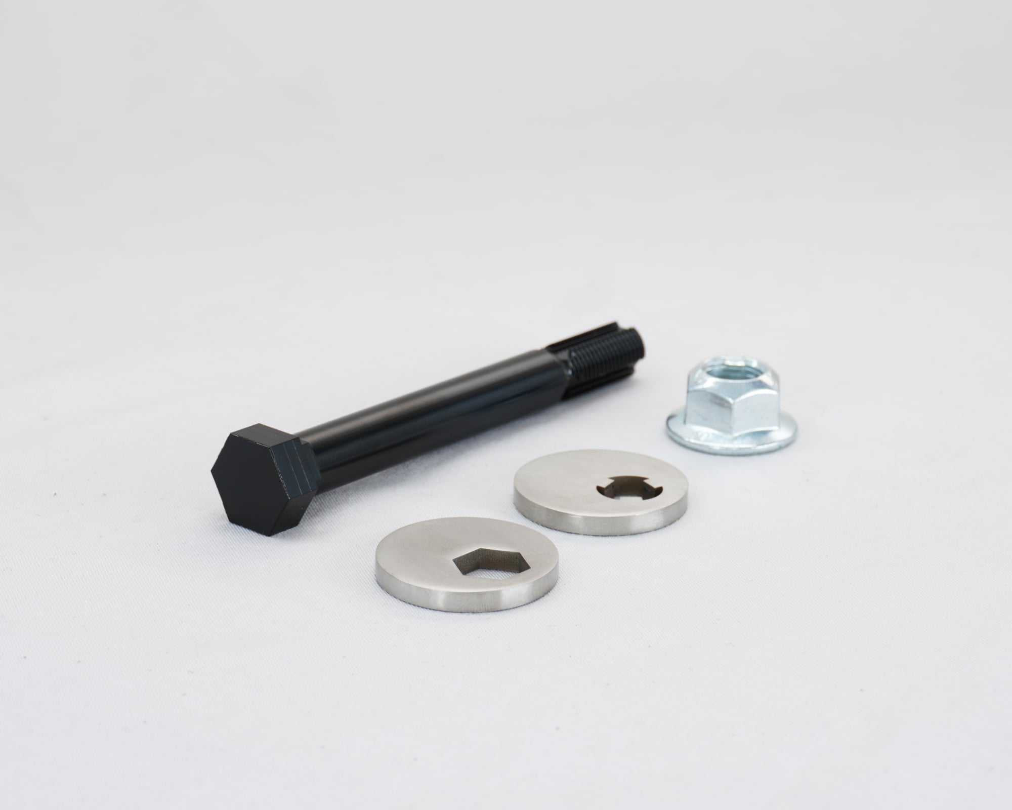
- The Triple Woodruff Key Design:
Our solution incorporates a triple Woodruff-style spline, which acts as the locking interface between the bolt and the cam plate. This provides deeper engagement, increased contact surface area, smaller and tighter tolerances between the components, all of which contribute to higher torsional resistance.

2. Increased Material Stiffness:
We chose to utilise high-carbon 12.9 grade steel for the bolt material long with stainless 304, zinc plated camberplate material to dramatically increase the stiffness coefficients of the mechansisms involved. A higher stiffness coefficient means that one can both tighten the bolt higher than with the equivalent OEM-spec, while also being able to expect higher resistance to moment/twisting forces that are invovled in hard cornering.
Experimental and FEA Testing
An Introduction to FEA
To get a better understanding of the mechanical differences between the OEM designs and our own, we conducted both computational Finite Element Analysis (FEA) and controlled physical torque testing. These two verification methods allow us to compare theoretical performance with real-world behaviour.
FEA:
Finite Element Analysis (FEA) is a computational based simulation method used by engineers to better understand how a component will behave under applied loads. The component is divided into small elements, and mathematical equations across those elements are solved to determine the distribution of stress, strain, deformation, stress concentrations and areas that may fail.
FEA essentially allows us to visualise a part flexing under loads and assess if the nature or the amount of flex is acceptable or not. For this study, we modelled all three camberbolt designs under itentical torsional loading conditions.


Simulation Method:
Because I wasn’t able to verify the material properties used to contruct the OEM bolts, I chose instead to focus on purely the mechanical properties of the bolt, to assess if any significant improvement had been made there. To ensure a fair comparison, the following constraints were applied equally to all the models:
- Identical material properties
- Identical boundary conditions
- Identical torsional load application
- Identical clamping constraints
The bolt shaft was constrainted to replicate its sealed position between the lower control arm and the conelock nut. A torsional moment was applied to the camberplate which simulates either the tightening torque as well as reprents the lateral loading inputted from the tyre.


FEA Output Observations
The simulations attached demonstrate the total deformation of the camberplate relative to its original geometry (see the wire-frame). From a quick visual inspection, it’s easy to identify the high deformation of the original OEM Mx-5 “D-Style” camberbolt assembly, as the small contact area forces load through the material, which accelerates failure.
The OEM “H-Style” camberbolt performs much better, with the extra thickness of the material alongside the two splines reinforce our observations well. With that said, it’s clear that there’s still flex in the component that can cause misalignment during high torsional loading activity – there’s room for improvement still.

Finally we come to the MXCB, the deformation with respect to the wireframe is proof that our design works well. The increased surface area and the reduced tolerances do well to lower peak stress concentrations while increasing more uniform and overal load distributions, all fo which result with a reduced total deformation of the camberplate under identical loads.
The FEA outputs align with the theoretical expectations and with what we have previous observed with OEM camberbolt designs.
Why Physical Testing Is Necessary
While FEA is a powerful engineering tool, it’s accuracy is a function of the correct load paths as well as material property inputs. Because the OEM camberbolt material specfications are not published or verifiable, I decided instead to conduct a controlled experiment to further validate these findings.
The purpose of the physical test was to replace the load scenarios, but also to compare the behaviour and fail characteristics of the camberbolt designs.
Experimental Methodology
Test Setup
To replicate real-world clamping conditions in a visual manner, we secured the bolt shaft using a bench vice, and installed a steel sleeve to replicate the lower control arm clamping surfaces. A calibrated torque wrench was used to apply rotational force through the conelock nut, whereby torque settings were increased incrementally while observing camberplate deformation.
Note the conelock nut with the larger flanged face was replaced with a standard nut, such that the incremental torque applied would be easier for us to control.

The camberplate was treated as the primary dependent variable, since it determines the alignment position. The independent variables were the torsional loads from the torque wrench, simulating torsional loads from hard cornering and braking.
Some Theory:
Materials tend to exhibit repeatable and predictable deformation characteristics that frame the way engineers design components. If we observe the figure below, we can see that all components have an elastic, plastic and a yield point.

The elastic region essentially means that while a component may twist under a load, it’ll return to it’s original position once the load is released. In the context of camberbolts, this would theoretically mean that the alignment shifts slightly during hard cornering, but returns to its original position once the car is pointing straight. Not ideal, not catatrophic, but to be expected.
Conversely, the plastic deformation region denotes the stress/strain a component can take where it has now permantely deformed. In the context of camberbolts, this would materialise in the camberplate flexing during a corner, such that the steering wheel isn’t quite straight once you’re heading in a straight line.
Here are some examples that demonstrate this in effect:
A catastrophic failure occurs at the fracture point of a component. This would materialise as the complete inability for the camberbolt assembly to hold any alignment, as the camberplate would theoretically spin under reduced loads. It was our goal to test both components until we reached that point, however, some oversight in the experimental setup in the clamping of the MXCB resulted with inconclusive results:

The vice clamping the MXCB bolt was mated only onto two opposing surfaces, whereas a spanner or socket would support the bolt using all six faces. This caused the head of the bold to deform before we could continue to observe any deformation in the camberplate, however we were already more than happy with the results, and decided to call it a day there.
Correlation Between FEA and Experimental Results
Between both studies, we found a lot of similarities between our FEA and experimental outputs:


OEM Mx-5 “D-Style” Camberplate, FEA Simulation Prediction vs. Experimental Output.


OEM Mx-5 “H-Style” Camberplate, FEA Simulation Prediction vs. Experimental Output.


HFM.Parts MXCB Camberplate, FEA Simulation Prediction vs. Experimental Output.
The visual comparions between both verification procedures are consistent with one another, and in doing so help point to the same engineering conclusion; the HFM.Parts MXCB is significantly better equipped to address Mx-5 misalignment caused by insufficient torsional resilience at the camberplate interface.
To summarise, this solution applies established mechanical engineering principles – improved load path design, increased engagement surface area, higher material strength and cross-validated verification methods, and solves this problem without adding any extra compromise to installation or adjustment.

