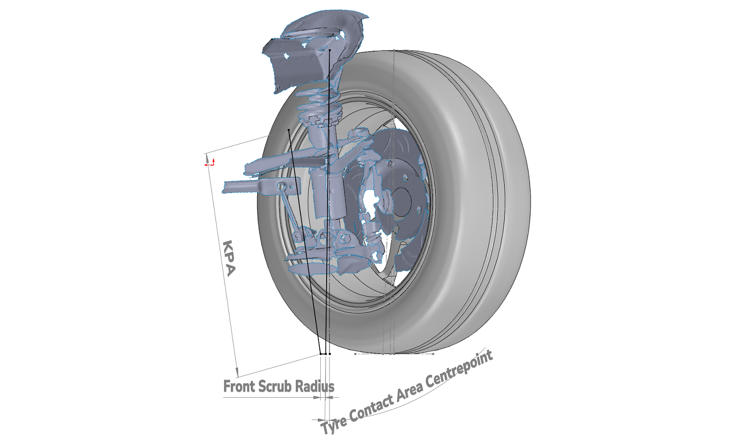
What is Scrub Radius?
Scrub radius is the distance between two important points on the ground.
- The first is the kingpin inclination axis (KPA). This is an imaginary line running through the pivot points of your suspension.
- The second is the tyre contact patch centreline. This is another imaginary line, perpendicular to the centre of where your tyre is contacting the ground surface.
The horizontal distance between these two points at the ground surface is measured, giving us the scrub radius coefficient.
Positive Scrub Radius: Kingpin inclination axis (extrapolated) hits the ground and is inboard of the tyre contact patch centreline.

Gaining “too much” positive scrub radius can amplify road noise, making the steering wheel stiff, twitchy and unpredictable, which negatively affects both turning and braking. It can also cause the wheel to gain positive camber when the wheels are turned, reducing cornering grip.
A “modest” positive scrub radius doesn’t typically see any noticeable negative performance characteristics. What defines “too much” or “modest” varies between chassis and modifications.
Negative Scrub Radius: Kingpin inclination axis (extrapolated) hits the ground and is outboard of the tyre contact patch centreline.

Generally, the most desirable of the three – tends to make the front wheels toe-in during loading conditions. This benefits braking and cornering predictability and stability.
Zero Scrub Radius: Kingpin inclination axis (extrapolated) intersects with the tyre contact patch centreline at ground surface.

The least desirable of the three – can cause squirm, which describes a scrubbing action occurring on both front tyres in opposing directions, producing more significant, unpredictable handling and braking characteristics, along with increased rolling resistance.
The reason we care about scrub radius is that it influences the dynamics of suspension geometry behaviour under heavy loads, particularly when discussing the influence of caster or toe. Understanding the scrub radius coefficients will ensure you don’t negatively affect acceleration, stability, braking and cornering aspects of your vehicle.
Why I’m Writing This
While reading online articles on wheel spacers and offset changes, I had difficulty understanding the various methods people employed to measure or calculate scrub radius for their own cars. Having modified my suspension, I also couldn’t use the factory numbers, so I set out to measure it myself.
This post outlines the method I came up with. It’s quite involved in that it combines 3D scanning and CAD software, both of which I’m familiar with. I want to stress that in 2025, neither technology is out of reach for the DIY enthusiast. Polycam (Smartphone) and Fusion 360 (Laptop/Computer) are two programs that are free to the DIY enthusiast and can be used in place of the equipment I’ve used here.
Alternatively, you could also adapt this method to suit simpler tools such as tape measures. This workflow generates more reliable, repeatable and visual results, which will be both easier to share here, as well as for future studies I’m interested in conducting.

Materials
- 3D Scanner
- Alternatively, a free phone 3D scanner will work (Polycam)
- CAD Software
- Fusion 360 is a great, accessible option
- Tools to Remove & Reinstall Wheel
- Wheel Socket
- Breaker Bar
- Torque Wrench
- Jack (Workshop Lift)
- Wooden Blocks (Jack)
Method
Step One: Vehicle Setup
- Start by breaking the lug nuts loose while the car is on the ground.
- Position wooden blocks or raise a jack under the lower control arm to replicate the ride height once the wheel is removed.
- Raise the car, remove the wheel, then lower it back onto the supports so that the suspension is sitting at normal ride height.
Note that this step is crucial – scrub radius depends heavily on the suspension geometry at ride height. You want the components statically loaded as they would be on the road.
Step Two: 3D Scan & Post-Processing
Front and Rear Suspension Components
- Now take a 3D scan of the inside of the suspension components, perpendicular to the hub.
- I set the precision to 1.2mm accuracy, which balances geometric accuracy with computational processing speeds.
")
- Process the 3D scan (if necessary).
- Reducing the number of elements/nodes and applying mesh optimisation processes also goes a long way to more efficiently loading and processing the scans on CAD software.
- I used the 3-2-1 (point, line, plane) alignment method to set axes before exporting as a .STL file. This makes accurate measuring and sketching on CAD programs easier.

Wheel
- Accurately capturing wheel geometry is equally important.
- You can do this via. obtaining dimensions (width, offset, tyre specs), but I opted to scan my wheel for direct overlay accuracy.
- Below is an example of my Advanti Storm S1 wheel overlaid with a CAD sketch.

Step Three: Establish Tyre Contact Patch
Paper Method
There are also multiple methods to obtain this coefficient. I tried two variations of what I’ll call the paper method, which involves either dropping or rolling the car onto a clean sheet of paper and observing the contact patch left. This produced inconclusive results for me:


Finding Tyre Contact Patch Centre: Drop Paper Method
Finding Tyre Contact Patch Centre: Roll Paper Method
The drop method I wouldn’t trust, as the suspension droops when unloaded, causing the wheels to gain positive camber while suspended. This means that when dropped onto the sheet of paper, the tyre contact patch wouldn’t be fully representative of the tyre contact patch. The rolling method is more theoretically accurate, but it produced vague, difficult-to-read results.
Camber & CAD Method
Instead, I grabbed a camber gauge (or take your most recent alignment sheet) and took measurements of my front and rear wheels, then drew lines on CAD to reflect the measurements and establish a tyre contact patch centre.


Step Four: CAD Processing and Line Tracing
- With the software tools I had accessible, my approach was simply to manually trace over the mesh to build usable geometry.
- For double-wishbone setups, define the two points at the outer ball joints and draw a line through them to represent the steering axis (as demonstrated).
- For MacPherson struts, trace a line through the strut top and lower ball joint.


Step Five: Establishing Scrub Radius Coefficient
- Combine the suspension and wheel assemblies.
- Extend the steering axis line to the ground.
- Measure the horizontal distance between the steering axis intersection and the tyre contact patch centreline.
This will give you the scrub radius:


Summary
This method should give a highly accurate approach to obtaining your vehicle’s scrub radius. Better yet, importing and processing the 3D scans into CAD also allows me to explore how more offset (whether that be through different wheel or spacer setups) will affect my scrub radius, allowing me to make informed decisions that are best for the longevity of the components as well as the dynamic performance of the vehicle.
For those interested, I’ll be following this up with a separate post exploring how spacers influence scrub radius, along with a host of other considerations, using this method as a baseline.
