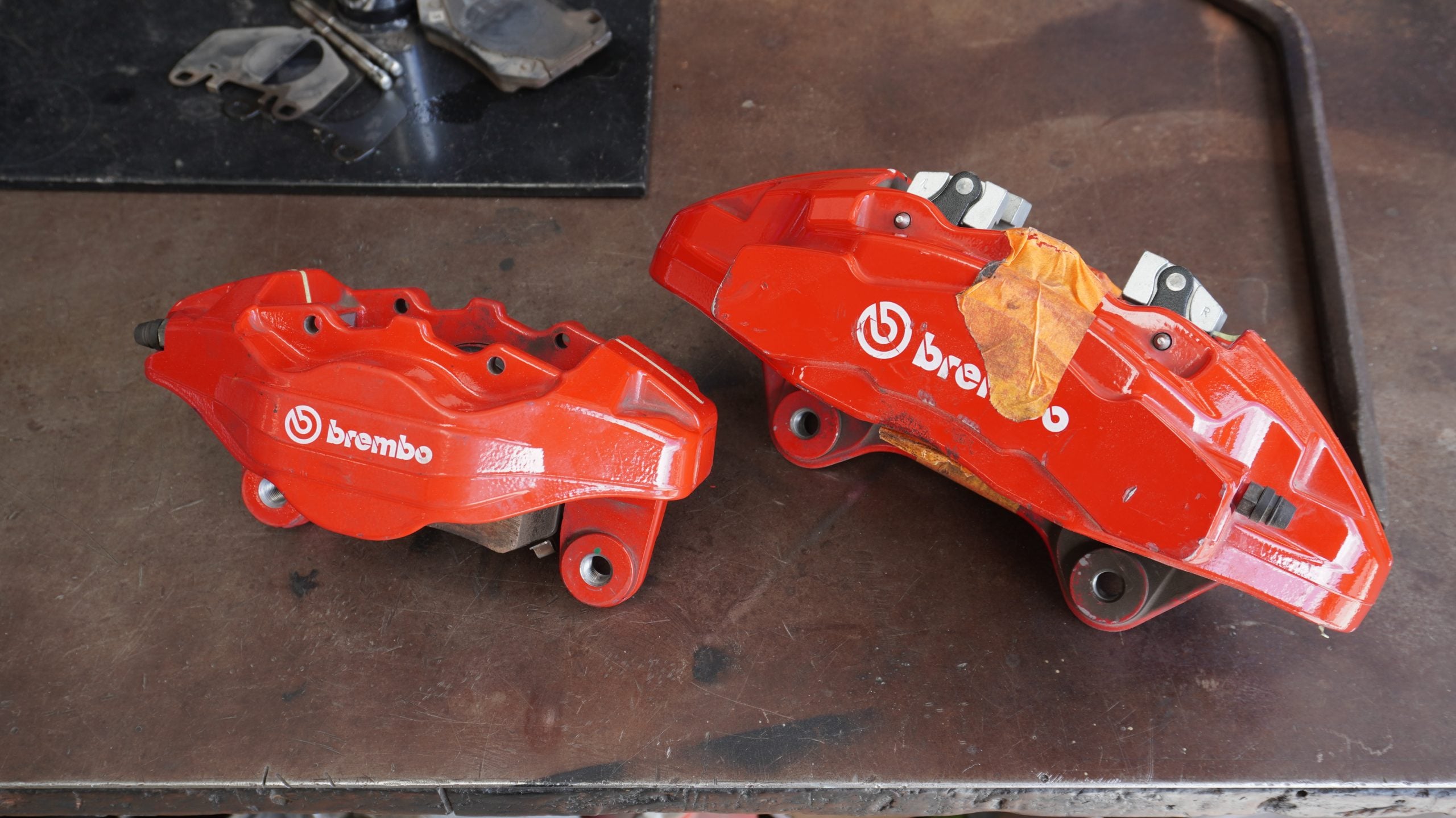
Late last year, we picked up a used set of Kia Stinger Brembo brake callipers for $350 – for a set of four! Naturally, we investigated whether these could be adapted into a better alternative to the existing popular brake kit solutions for the Skyline and Silvia chassis. This post shares technical insights into what those considerations were, and highlights why we’re so stoked about this kit.
Understanding the Ideal Brake Curve
People often mistaken in thinking bigger brakes will make them stop quicker. Braking distances are a function of how much tyre grip is available, so if we want to reduce braking distances, we need to try to maximise tyre grip when braking. To do so, let’s start with understanding these four variables:
- Vehicle weight
- F/R weight distribution
- Height of COG
- Wheelbase length
The reason we care about these variables is that during braking, the car effectively pivots about its CoG, unloading the rear and transferring that forward. I’ve drawn up some diagrams below – unfortunately, I don’t have any flicks of Skylines, so this Mx-5 will have to do.


This hopefully lends perspective as to why tyre grip dictates brake balance. You can see here that as the weight unloads from the rear and onto the front, the grip levels do the same. If we were to apply the same braking force to all four wheels, we would either be locking up the rear brakes (applying too much force for the grip available) or applying too little force on the fronts, which would dramatically increase the stopping distance.
Naturally, an Mx-5 with a shorter wheelbase, low CoG height, reduced mass and different F/R axle mass will exhibit different dynamic properties to a Skyline or Silvia. We can visualise this. Engineers model the behaviour of these variables with an “Ideal Brake Curve” graph as demonstrated below. The diagonal lines represent the increasing levels of grip, the x-axis and y-axis displaying the front and rear brake force, respectively. Visualising this information, you can start to see that the front brake force required rises disproportionately the harder you brake. For FWD cars, this becomes even more exaggerated, which is why front-heavy vehicles don’t typically run large rear brake components.

While this is helpful for better understanding the dynamic behaviour of a vehicle under a broad spectrum of braking conditions, it’s still only the starting point. The modelling methods I’ve listed here can’t account for all the variables that can affect this behaviour (tyre wear, fuel load, etc.), so we treat this as a method to ‘crudely’ set up the brakes, such that we can finetune the balance using alternative methods later on.
Some Ways to Adjust Brake Balance
There are multiple ways to adjust brake balance on a vehicle, but best practices follow a hierarchy of what steps to take first. It’s best to start off with the geometric components, as they’re not adjustable and they also provide accessory benefits (read my blogpost on rotor kits). Only once you’re close to your desired balance should you start looking to rely on the finetuning elements.
Baseline Balance
Geometric Bias: Effective Rotor Diameter
This is where I start – larger rotors not only increase the effective radius, but also offer a better surface area: volume ratio to manage heat more effectively.
Geometric Bias: Calliper Piston/Pad Area
This is a function of how many and how large the pistons (on one side) a calliper has. The calliper pad area dictates the clamping force onto the rotor. This is a key area to dictate early on, as larger pads will resist heat better.
Finetuning Balance
Hydraulic Bias: Brake Bias Valves
These are invaluable for fine-tuning, but I would avoid using them for setting the foundation of the balance. Once the system is geometrically sound, a proportioning valve can be used to make small adjustments to suit track and vehicle conditions.
Mechanical Bias: Staggered Pad Compounds
It’s not uncommon to see staggered pad compounds between the front and rear axles on motorsport vehicles, as it also helps to fine-tune a balance setup. By installing a more aggressive setup on the rear, you essentially increase the clamping force, thus also the brake balance.
What Do I Do With This Information?
So where does this leave us? We now understand why we need to set a geometrically proportionate baseline, so let’s compare the HFM.Parts RSBREMB brake kits with an existing OEM Nissan brake setup.
For this study, I chose the R34 GTR equipped with the 324mm front and 322mm Brembo brakes. The other skylines vary with their brake setups, but I noticed that a lot share the same rotor sizes – I’m suspecting this was to cater towards more cost-savings than peak performance, hence why I was more attracted to compare with the GTR setup.
To reiterate, the goal here is to establish a baseline setup for the brakes. Once this is established, the following finetuning steps to dial in your brake performance become much more intuitive.
Calculations and Measurements:
To assess how effective the Kia Stinger Brembo calliper worked on the Skyline Chassis, I grabbed the following measurements and equations:
Piston Area (PA)
Piston area is taken by first taking the diameter of the pistons in the calliper. Note that some callipers have smaller-diameter leading pistons. Using the following method, you can find your piston area:

Once your piston diameters are obtained, use the following equation to calculate your piston area.
An important note: In the two-piston, fixed calliper shown, I take only the area of the piston on one side of the calliper, not both. A common misconception is that floating-style callipers only provide half the brake force – this is incorrect. Neglecting any mechanical losses, floating-style callipers work by creating opposite and equal (normal) forces using the sliding mechanism. This is why we only take piston measurements from one side of the calliper, regardless of its mechanical properties.
Effective Rotor Radius (ERR)
Because the centre of the piston is where most of the clamping force is applied, we take the “effective” radius, which is essentially the distance from the centre of the rotor to the centre of the brake calliper pistons/pads when assembled.
The image on the left here shows a very inefficient method for calculating the effective rotor radius, but hopefully demonstrates my points visually. On the right, I’ve taken an image displaying my preferred method for finding effective rotor radius; you can do at home.


Now, I just run my brake calculations minus all of the constants. In doing so, I end up with something that looks like this:
| R34 GTR Brembo Brakes | Kia Stinger Brembo Brakes | |
| Front Calliper Piston Area (mm^2) (FPA) | 5554 | 4549 |
| Rear Calliper Piston Area (mm^2) (RPA) | 2268 | 1815 |
| Front Rotor Effective Radius (mm) (FERR) | 125.15 | 145 |
| Rear Rotor Effective Radius (mm) (RERR) | 128.25 | 149 |
| Front Brake Force (FPA*FERR) | 695083.1 | 659605 |
| Rear Brake Force (RPA*RERR) | 290871 | 270435 |
| F/R Balance | 2.389661052 | 2.439051898 |
| F/R Balance Delta (%) | 2.066855687 |
What these calculations show is an overall ~2% difference in F/R brake balance between the R34 GTR Brakes and the Kia Stinger Brembo Brake Kit by HFM.Parts, which I would personally call a negligible difference, especially when you’re considering the performance benefits. To prove it, have a look at the difference in overall geometric brake bias balance.
OEM F/R Geometric Brake Bias Balance:
70.5: 29.5
HFM.Parts F/R Geometric Brake Bias Balance:
70.9: 29.1
Summary
The theory on this page highlights what elements are important to consider with brake kits, and they also demonstrate that theory applied to our latest Kia Stinger Brembo callipers for Nissan Skylines. This post discusses a common method to understand geometric brake force distributions and applies them to understand the HFM.Parts RSMREMB brake kit is a good candidate for Skylines and Silvia’s by calculating and comparing both of their geometric brake bias balance. Not only was the difference found to be negligible, but the price of the components is significantly less, while also demanding less mechanical work and reduced thermal loading.
The overall snapshot is a brake kit that promises higher performance, likely higher reliability, and increased longevity, all at a reduced cost – not bad?
Brake setups don’t stop here. Upcoming blog posts will cover further finetuning your brakes – explaining why it’s relevant while also outlining the various methods you can go about doing so.

