Introduction:
This guide outlines the unique steps to install the RS354AKE for your R32 Nissan Skyline. Note that this particular set of instructions is done on the Skyline, but the same process applies for the Nissan Silvia.
Installation Steps
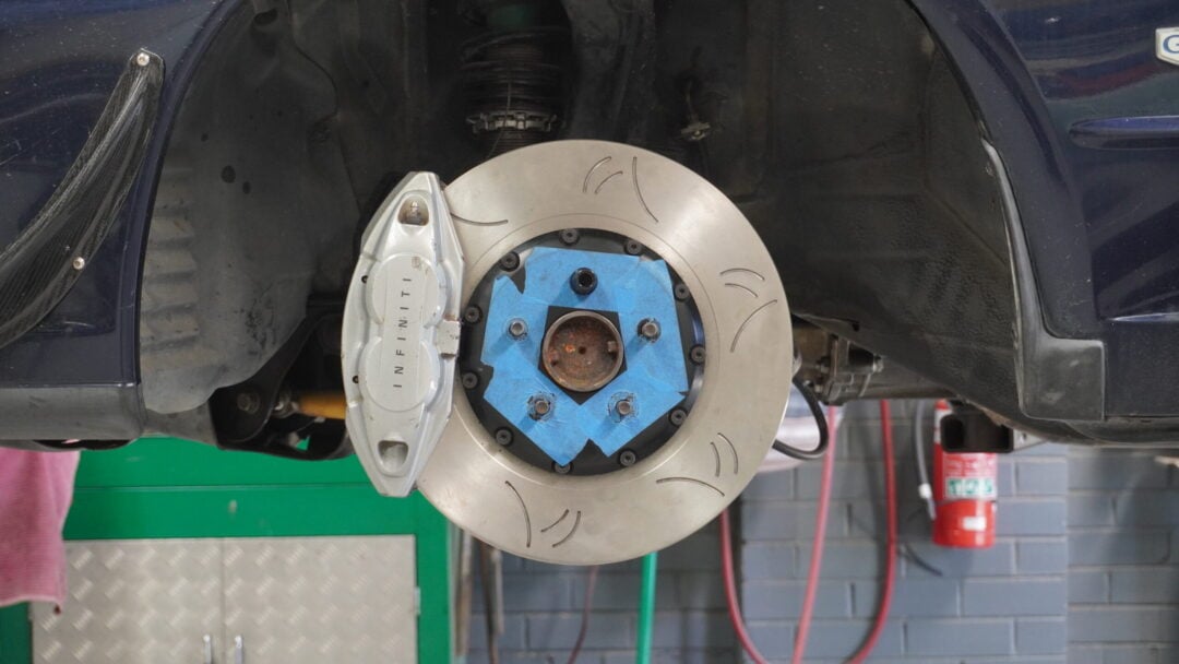
Step 1: Remove Calliper Material (Optional)
In an attempt to create a lightweight rotor and considering the outer ring is the heaviest component, we’ve enlarged the aluminium centre hat as much as possible so that we could reduce the rotor surface. This means that the centre hat sits quite close to the caliper and during heavy track work has the potential to expand and skim the caliper. We recommend linishing a very small portion of the caliper to accommodate for this. (photo example shown below). Die-grind a 10mm x 20mm section of the brake calliper in the area highlighted in red with lines.
*If you are using an OEM 354mm 1-piece rotor, there will be sufficient clearance, and no die-grinding is needed.
Step 2: Remove Existing Components
1. Lift the vehicle and remove the front wheels.
2. Detach the brake calliper and remove the brake rotor from the front knuckle.
3. Remove the brake line and caliper now, or remove them towards the end.
4. You may also need to remove or modify your backing plate.
Step 3: Attach Caliper Adaptor Bracket
The adapters are labelled as follows:
RS354AKE-L and RS354AKE-R
L – Left Hand & R – Right Hand
Use the provided M12 bolts with washers. Use the 70mm Hex head, with the half-moon spacer on top, and the 40mm on the bottom. Do not fully tighten.
Step 4: Position Support Spacer with Caliper
Using the 70mm Bolt and 28mm Spacer, mount the Adaptor, making sure the cut-out of the spacer is facing the caliper. This will help to align the Caliper’s top mounting hole to rest into the spacer’s cut-out. Then, tighten both the top and bottom bolts properly – but without using the torque wrench, as we will be removing the Caliper again. This will set the Support Spacer up to be torqued into place.
Then, torque the Caliper Adaptor bolts at 58 – 62 ft-lbs, which will also lock the Support Spacer into place.
Step 5: Install Rotor and Brake Calliper
Remove the Caliper and install the rotor, holding it in place using a lug nut.
Re-install the Caliper and torque both bolts to 58 – 62 ft lbs.
Lastly, check for clearance between the backing plate and the rotor. If there is any interference, bend the backing plate out of the way.
Step 6: Install Brake Line
Your OEM brake lines will be at full extension when using this adaptor/brake kit. We highly recommend using HFM.Parts Front Braided Brake Lines of your choice.
Position the brake line carefully to avoid contact with moving or sharp components.
Secure the brake line clip back into the mounting blocks and clip it in place.
Step 8: Install the Brake Pads
Slide the brake pads into place and insert the two bridging pins
Lock in the bridge pins with the metal R-clips
Final Checks
– Double-check all bolts and fittings for tightness.
– Ensure the brake lines are not rubbing against any components.
– Bleed the brakes to remove air from the system.
– Perform a test drive at low speeds to verify proper braking function.


